Review: S5648X-2Q4Z Switch - Part 1: VxLAN/GENEVE/NvGRE
After receiving an e-mail from a newer [China based switch OEM], I had a chat with their founder and learned that the combination of switch silicon and software may be a good match for IPng Networks. You may recall my previous endeavors in the Fiberstore lineup, notably an in-depth review of the [S5860-20SQ] which sports 20x10G, 4x25G and 2x40G optics, and its larger sibling the S5860-48SC which comes with 48x10G and 8x100G cages. I use them in production at IPng Networks and their featureset versus price point is pretty good. In that article, I made one critical note reviewing those FS switches, in that they’e be a better fit if they allowed for MPLS or IP based L2VPN services in hardware.
I got cautiously enthusiastic (albeit suitably skeptical) when this new vendor claimed VxLAN, GENEVE, MPLS and GRE at 56 ports and line rate, on a really affordable budget (sub-$4K for the 56 port; and sub-$2K for the 26 port switch). This reseller is using a less known silicon vendor called [Centec], who have a lineup of ethernet silicon. In this device, the CTC8096 (GoldenGate) is used for cost effective high density 10GbE/40GbE applications paired with 4x100GbE uplink capability. This is Centec’s fourth generation, so CTC8096 inherits the feature set from L2/L3 switching to advanced data center and metro Ethernet features with innovative enhancement. The switch chip provides up to 96x10GbE ports, or 24x40GbE, or 80x10GbE + 4x100GbE ports, inheriting from its predecessors a variety of features, including L2, L3, MPLS, VXLAN, MPLS SR, and OAM/APS. Highlights features include Telemetry, Programmability, Security and traffic management, and Network time synchronization.
This will be the first of a set of write-ups exploring the hard- and software functionality of this new vendor. As we’ll see, it’s all about the software.
Detailed findings
Hardware
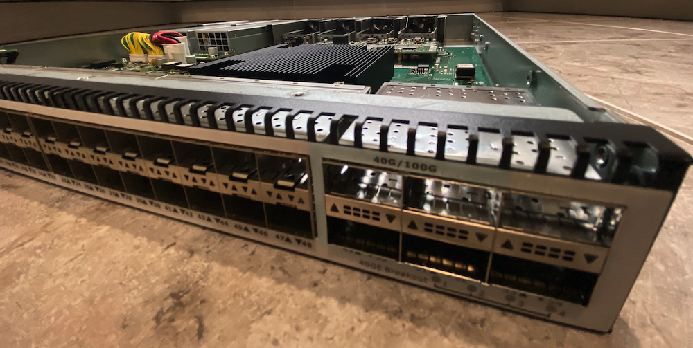
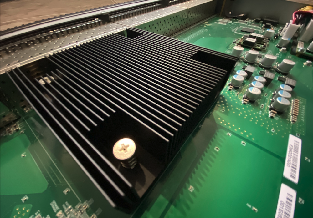
The switch comes well packaged with two removable 400W Gold powersupplies from Compuware Technology which output 12V/33A and +5V/3A as well as four removable PWM controlled fans from Protechnic. The fans are expelling air, so they are cooling front-to-back on this unit. Looking at the fans, changing them to pull air back-to-front would be possible after-sale, by flipping the fans around as they’re attached in their case by two M4 flat-head screws. This is truly meant to be an OEM switch – there is no logo or sticker with the vendor’s name, so I should probably print a few vinyl IPng stickers to skin them later.
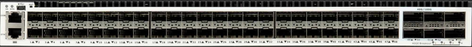
On the front, the switch sports an RJ45 standard serial console, a mini-usb connector of which the
function is not clear to me, an RJ45 network port used for management, a pinhole which houses a
reset button labeled RST and two LED indicators labeled ID and SYS. The serial port runs at
115200,8n1 and the managment network port is Gigabit.
Regarding the regular switch ports, there are 48x SFP+ cages, 4x QSFP28 (port 49-52) runing at
100Gbit, and 2x QSFP+ ports (53-54) running at 40Gbit. All ports (management and switch) present a
MAC address from OUI 00-1E-08, which is assigned to Centec.
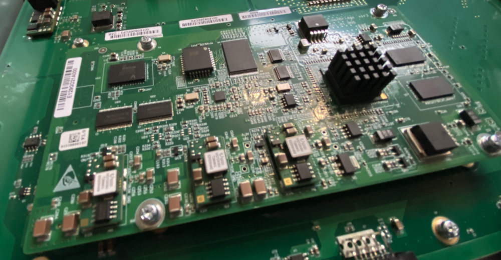
The switch is not particularly quiet, as its six fans total start up at a high pitch but once the switch boots, they calm down and emit noise levels as you would expect from a datacenter unit. I measured it at 74dBA when booting, and otherwise at around 62dBA when running. On the inside, the PCB is rather clean. It comes with a daughter board, housing a small PowerPC P1010 with 533MHz CPU, 1GB of RAM, and 2GB flash on board, which is running Linux. This is the same card that many of the FS.com switches use (eg. S5860-48S6Q), a cheaper alternative to the high end Intel Xeon-D.
S5648X (48x10, 2x40, 4x100)
There is one switch chip, on the front of the PCB, connecting all 54 ports. It has a sizable heatsink on it, drawing air backwards through ports (36-48). The switch uses a less well known and somewhat dated Centec [CTC8096], codenamed GoldenGate and released in 2015, which is rated for 1.2Tbps of aggregate throughput. The chip can be programmed to handle a bunch of SDN protocols, including VxLAN, GRE, GENEVE, and MPLS / MPLS SR, with a limited TCAM to hold things like ACLs, IPv4/IPv6 routes and MPLS labels. The CTC8096 provides up to 96x10GbE ports, or 24x40GbE, or 80x10GbE + 4x100GbE ports. The SerDES design is pretty flexible, allowing it to mix and match ports.
You can see more (hires) pictures and screenshots throughout these articles in this [Photo Album].
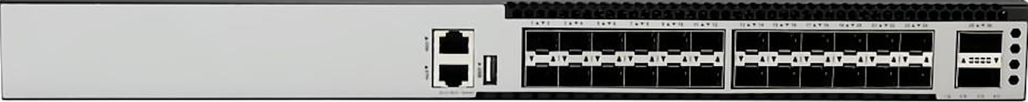
S5624X (24x10, 2x100)
In case you’re curious (I certainly was!) the smaller unit (with 24x10+2x100) is built off of the Centic [CTC7132], codenamed TsingMa which released in 2019, and it offers a variety of similar features, including L2, L3, MPLS, VXLAN, MPLS SR, and OAM/APS. Highlights features include Telemetry, Programmability, Security and traffic management, and Network time synchronization. The SoC has an embedded ARM A53 CPU Core running at 800MHz, and the SerDES on this chip allows for 24x1G/2.5G/5G/10G and 2x40G/100G for a throughput of 440Gbps but at a failry sharp price point.
One thing worth noting (because I know some of my regular readers will already be wondering!) this series of chips (both the 4th generation CTC8096 and the sixth generation CTC7132) come with a very modest TCAM, which means in practice 32K MAC addresses, 8K IPv4 routes, 1K IPv6 routes, a 6K MPLS table, 1K L2VPN instances, and 64 VPLS instances. The Centec comes as well with a modest 32MB packet buffer shared between all ports, and the controlplane comes with 1GB of memory and a 533MHz ARM. So no, this won’t take a full table :-) but in all honesty, that’s not the thing this machine is built to do.
When booted, the switch draws roughly 68 Watts combined on its two power supplies, and I find that pretty cool considering the total throughput offered. Of course, once optics are inserted, the total power draw will go up. Also worth noting, when the switch is under load, the Centec chip will consume more power, for example when forwarding 8x10G + 2x100G, the total consumption was 88 Watts, totally respectable now that datacenter power bills are skyrocketing.
Topology

On the heals of my [DENOG14 Talk], in which I showed how VPP can route 150Mpps and 180Gbps on a 10 year old Dell while consuming a full 1M BGP table in 7 seconds or so, I still had a little bit of a LAB left to repurpose. So I build the following topology using the loadtester, packet analyzer, and switches:
- msw-top: S5624-2Z-EI switch
- msw-core: S5648X-2Q4ZA switch
- msw-bottom: S5624-2Z-EI switch
- All switches connect to:
- each other with 100G DACs (right, black)
- T-Rex machine with 4x10G (left, rainbow)
- Each switch gets a mgmt IPv4 and IPv6
With this topology I will have enough wiggle room to patch anything to anything. Now that the physical part is out of the way, let’s take a look at the firmware of these things!
Software
As can be seen in the topology above, I am testing three of these switches - two are the smaller sibling [S5624X 2Z-EI] (which come with 24x10G SFP+ and 2x100G QSFP28), and one is this [S5648X 2Q4Z] pictured above. The vendor has a licensing system, for basic L2, basic L3 and advanced metro L3. These switches come with the most advanced/liberal licenses, which means all of the features will work on the switches, notably, MPLS/LDP and VPWS/VPLS.
Taking a look at the CLI, it’s very Cisco IOS-esque; there’s a few small differences, but the look and feel is definitely familiar. Base configuration kind of looks like this:
Basic config
msw-core# show running-config
management ip address 192.168.1.33/24
management route add gateway 192.168.1.252
!
ntp server 216.239.35.4
ntp server 216.239.35.8
ntp mgmt-if enable
!
snmp-server enable
snmp-server system-contact noc@ipng.ch
snmp-server system-location Bruttisellen, Switzerland
snmp-server community public read-only
snmp-server version v2c

msw-core# conf t
msw-core(config)# stm prefer ipran
A few small things of note. There is no mgmt0 device as I would’ve expected. Instead, the SoC
exposes its management interface to be configured with these management ... commands. The IPv4 can
be either DHCP or a static address, and IPv6 can only do static addresses. Only one (default)
gateway can be set for either protocol. Then, NTP can be set up to work on the mgmt-if which is a
useful way to use it for timekeeping.
The SNMP server works both from the mgmt-if and from the dataplane, which is nice.
SNMP supports everything you’d expect, including v3 and traps for all sorts of events, including
IPv6 targets and either dataplane or mgmt-if.
I did notice that the nameserver cannot use the mgmt-if, so I left it unconfigured. I found it a
little bit odd, considering all the other functionality does work just fine over the mgmt-if.
If you’ve run CAM-based systems before, you’ll likely have come across some form of partitioning
mechanism, to allow certain types in the CAM (eg. IPv4, IPv6, L2 MACs, MPLS labels, ACLs) to have
more or fewer entries. This is particularly relevant on this switch because it has a comparatively
small CAM. It turns out, that by default MPLS is entirely disabled, and to turn it on (and sacrifice
some of that sweet sweet content addressable memory), I have to issue the command stm prefer ipran
(other flavors are ipv6, layer3, ptn, and default), and reload the switch.
Having been in the networking industry for a while, I scratched my head on the acronym IPRAN, so I will admit having to look it up. It’s a general term used to describe an IP based Radio Access Network (2G, 3G, 4G or 5G) which uses IP as a transport layer technology. I find it funny in a twisted sort of way, that to get the oldskool MPLS service, I have to turn on IPRAN.
Anyway, after changing the STM profile to ipran, the following partition is available:
| IPRAN CAM | S5648X (msw-core) | S5624 (msw-top & msw-bottom) |
|---|---|---|
| MAC Addresses | 32k | 98k |
| IPv4 routes | host: 4k, indirect: 8k | host: 12k, indirect: 56k |
| IPv6 routes | host: 512, indirect: 512 | host: 2048, indirect: 1024 |
| MPLS labels | 6656 | 6144 |
| VPWS instances | 1024 | 1024 |
| VPLS instances | 64 | 64 |
| Port ACL entries | ingress: 1927, egress: 176 | ingress: 2976, egress: 928 |
| VLAN ACL entries | ingress: 256, egress: 32 | ingress: 256, egress: 64 |
First off: there’s quite a few differences here! The big switch has relatively few MAC, IPv4 and IPv6 routes, compared to the little ones. But, it has a few more MPLS labels. ACL wise, the small switch once again has a bit more capacity. But, of course the large switch has lots more ports (56 versus 26), and is more expensive. Choose wisely :)
Regarding IPv4/IPv6 and MPLS space, luckily [AS8298] is relatively compact in its IGP. As of today, it carries 41 IPv4 and 48 IPv6 prefixes in OSPF, which means that these switches would be fine participating in Area 0. If CAM space does turn into an issue down the line, I can put them in stub areas and advertise only a default. As an aside, VPP doesn’t have any CAM at all, so for my routers the size is basically goverened by system memory (which on modern computers equals “infinite routes”). As long as I keep it out of the DFZ, this switch should be fine, for example in a BGP-free core that switches traffic based on VxLAN or MPLS, but I digress.
L2
First let’s test a straight forward configuration:
msw-top# configure terminal
msw-top(config)# vlan database
msw-top(config-vlan)# vlan 5-8
msw-top(config-vlan)# interface eth-0-1
msw-top(config-if)# switchport access vlan 5
msw-top(config-vlan)# interface eth-0-2
msw-top(config-if)# switchport access vlan 6
msw-top(config-vlan)# interface eth-0-3
msw-top(config-if)# switchport access vlan 7
msw-top(config-vlan)# interface eth-0-4
msw-top(config-if)# switchport mode dot1q-tunnel
msw-top(config-if)# switchport dot1q-tunnel native vlan 8
msw-top(config-vlan)# interface eth-0-26
msw-top(config-if)# switchport mode trunk
msw-top(config-if)# switchport trunk allowed vlan only 5-8
By means of demonstration, I created port eth-0-4 as a QinQ capable port - which means that any
untagged frames coming into it will become VLAN 8, but any tagged frames will become s-tag 8 and
c-tag with whatever tag was sent, in other words standard issue QinQ tunneling. The configuration
of msw-bottom is exactly the same, and because we’re connecting these VLANs through msw-core,
I’ll have to make it a member of all these interfaces using the interface range shortcut:
msw-core# configure terminal
msw-core(config)# vlan database
msw-core(config-vlan)# vlan 5-8
msw-core(config-vlan)# interface range eth-0-49 - 50
msw-core(config-if)# switchport mode trunk
msw-core(config-if)# switchport trunk allowed vlan only 5-8
The loadtest results in T-Rex are, quite unsurprisingly, line rate. In the screenshot below, I’m
sending 128 byte frames at 8x10G (40G from msw-top through msw-core and out msw-bottom, and
40G in the other direction):
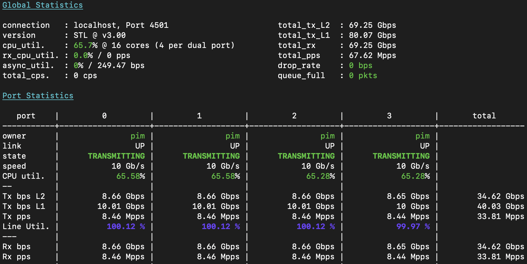
A few notes, for critical observers:
- I have to use 128 byte frames because the T-Rex loadtester is armed with 3x Intel x710 NICs, which have a total packet rate of 40Mpps only. Intel made these with LACP redundancy in mind, and do not recommend fully loading them. As 64b frames would be ~59.52Mpps, the NIC won’t keep up. So, I let T-Rex send 128b frames, which is ~33.8Mpps.
- T-Rex shows only the first 4 ports in detail, and you can see all four ports are sending 10Gbps of L1 traffic, which at this frame size is 8.66Gbps of ethernet (as each frame also has a 24 byte overhead [ref]). We can clearly see though, that all Tx packets/sec are also Rx packets/sec, which means all traffic is safely accounted for.
- In the top panel, you will see not 4x10, but 8x10Gbps and 67.62Mpps of total throughput, with no traffic lost, and the loadtester CPU well within limits: 👍
msw-top# show int summary  | exc DOWN
RXBS: rx rate (bits/sec)        RXPS: rx rate (pkts/sec)
TXBS: tx rate (bits/sec)        TXPS: tx rate (pkts/sec)

Interface    Link  RXBS          RXPS          TXBS          TXPS
-----------------------------------------------------------------------------
eth-0-1      UP    10016060422   8459510       10016060652   8459510
eth-0-2      UP    10016080176   8459527       10016079835   8459526
eth-0-3      UP    10015294254   8458863       10015294258   8458863
eth-0-4      UP    10016083019   8459529       10016083126   8459529
eth-0-25     UP    449           0             501           0
eth-0-26     UP    41362394687   33837608      41362394527   33837608
Clearly, all three switches are happy to forward 40Gbps in both directions, and the 100G port is happy to forward (at least) 40G symmetric - and because the uplink port is trunked, each ethernet frame will be 4 bytes longer due to the dot1q tag, which, at 128b frames means we’ll be using 132/128 * 4 * 10G == 41.3G of traffic, which it spot on.
L3
For this test, I will reconfigure the 100G ports to become routed rather than switched. Remember,
msw-top connects to msw-core, which in turn connects to msw-bottom, so I’ll need two IPv4 /31
and two IPv6 /64 transit networks. I’ll also create a loopback interface with a stable IPv4 and IPv6
address on each switch, and I’ll tie all of these together in IPv4 and IPv6 OSPF in Area 0. The
configuration for the msw-top switch becomes:
msw-top# configure terminal
interface loopback0
 ip address 172.20.0.2/32
 ipv6 address 2001:678:d78:400::2/128
 ipv6 router ospf 8298 area 0
!
interface eth-0-26
 description Core: msw-core eth-0-49
 speed 100G
 no switchport
 mtu 9216
 ip address 172.20.0.11/31
 ipv6 address 2001:678:d78:400::2:2/112
 ip ospf network point-to-point
 ip ospf cost 1004
 ipv6 ospf network point-to-point
 ipv6 ospf cost 1006
 ipv6 router ospf 8298 area 0
!
router ospf 8298
 router-id 172.20.0.2
 network 172.20.0.0/22 area 0
 redistribute static
!
router ipv6 ospf 8298
 router-id 172.20.0.2
 redistribute static
Now that the IGP is up for IPv4 and IPv6 and I can ping the loopbacks from any switch to any other switch, I can continue with the loadtest. I’ll configure four IPv4 interfaces:
msw-top# configure terminal
interface eth-0-1
 no switchport
 ip address 100.65.1.1/30
!
interface eth-0-2
 no switchport
 ip address 100.65.2.1/30
!
interface eth-0-3
 no switchport
 ip address 100.65.3.1/30
!
interface eth-0-4
 no switchport
 ip address 100.65.4.1/30
!
ip route 16.0.1.0/24 100.65.1.2
ip route 16.0.2.0/24 100.65.2.2
ip route 16.0.3.0/24 100.65.3.2
ip route 16.0.4.0/24 100.65.4.2
After which I can see these transit networks and static routes propagate, through msw-core, and
into msw-bottom:
msw-bottom# show ip route
Codes: K - kernel, C - connected, S - static, R - RIP, B - BGP
       O - OSPF, IA - OSPF inter area
       N1 - OSPF NSSA external type 1, N2 - OSPF NSSA external type 2
       E1 - OSPF external type 1, E2 - OSPF external type 2
       i - IS-IS, L1 - IS-IS level-1, L2 - IS-IS level-2, ia - IS-IS inter area
       Dc - DHCP Client
       [*] - [AD/Metric]
       * - candidate default

O        16.0.1.0/24 [110/2013] via 172.20.0.9, eth-0-26, 05:23:56
O        16.0.2.0/24 [110/2013] via 172.20.0.9, eth-0-26, 05:23:56
O        16.0.3.0/24 [110/2013] via 172.20.0.9, eth-0-26, 05:23:56
O        16.0.4.0/24 [110/2013] via 172.20.0.9, eth-0-26, 05:23:56
O        100.65.1.0/30 [110/2010] via 172.20.0.9, eth-0-26, 05:23:56
O        100.65.2.0/30 [110/2010] via 172.20.0.9, eth-0-26, 05:23:56
O        100.65.3.0/30 [110/2010] via 172.20.0.9, eth-0-26, 05:23:56
O        100.65.4.0/30 [110/2010] via 172.20.0.9, eth-0-26, 05:23:56
C        172.20.0.0/32 is directly connected, loopback0
O        172.20.0.1/32 [110/1005] via 172.20.0.9, eth-0-26, 05:50:48
O        172.20.0.2/32 [110/2010] via 172.20.0.9, eth-0-26, 05:23:56
C        172.20.0.8/31 is directly connected, eth-0-26
C        172.20.0.8/32 is in local loopback, eth-0-26
O        172.20.0.10/31 [110/1018] via 172.20.0.9, eth-0-26, 05:50:48
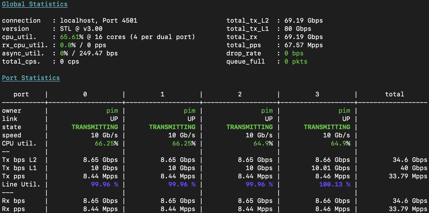
I now instruct the T-Rex loadtester to send single-flow loadtest traffic from 16.0.X.1 -> 48.0.X.1 on port 0; and back from 48.0.X.1 -> 16.0.X.1 on port 1; and then for port2+3 I use X=2, for port4+5 I will use X=3, and port 6+7 I will use X=4. After T-Rex starts up, it’s sending 80Gbps of traffic with a grand total of 67.6Mpps in 8 unique flows of 8.45Mpps at 128b each, and the three switches forward this L3 IPv4 unicast traffic effortlessly:
Overlay
What I’ve built just now would be acceptable really only if the switches were in the same rack (or at best, facility). As an industry professional, I frown upon things like VLAN-stretching, a term that describes bridging VLANs between buildings (or, as some might admit to .. between cities or even countries🤮). A long time ago (in December 1999), Luca Martini invented what is now called [Martini Tunnels], defining how to transport Ethernet frames over an MPLS network, which is what I really want to demonstrate, albeit in the next article.
What folks don’t always realize is that the industry is moving on from MPLS to a set of more flexible IP based solutions, notably tunneling using IPv4 or IPv6 UDP packets such as found in VxLAN or GENEVE, two of my favorite protocols. This certainly does cost a little bit in VPP, as I wrote about in my post on [VLLs in VPP], although you’d be surprised how many VxLAN encapsulated packets/sec a simple AMD64 router can forward. With respect to these switches, though, let’s find out if tunneling this way incurs an overhead or performance penalty. Ready? Let’s go!
First I will put the first four interfaces in range eth-0-1 - 4 into a new set of VLANs, but in the
VLAN database I will enable what is called overlay on them:
msw-top# configure terminal
vlan database
 vlan 5-8,10,20,30,40
 vlan 10 name v-vxlan-xco10
 vlan 10 overlay enable
 vlan 20 name v-vxlan-xco20
 vlan 20 overlay enable
 vlan 30 name v-vxlan-xco30
 vlan 30 overlay enable
 vlan 40 name v-vxlan-xco40
 vlan 40 overlay enable
!
interface eth-0-1
 switchport access vlan 10
!
interface eth-0-2
 switchport access vlan 20
!
interface eth-0-3
 switchport access vlan 30
!
interface eth-0-4
 switchport access vlan 40
Next, I create two new loopback interfaces (bear with me on this one), and configure the transport of these overlays in the switch. This configuration will pick up the VLANs and move them to remote sites in either VxLAN, GENEVE or NvGRE protocol, like this:
msw-top# configure terminal
!
interface loopback1
 ip address 172.20.1.2/32
!
interface loopback2
 ip address 172.20.2.2/32
!
overlay
 remote-vtep 1 ip-address 172.20.0.0 type vxlan src-ip 172.20.0.2
 remote-vtep 2 ip-address 172.20.1.0 type nvgre src-ip 172.20.1.2
 remote-vtep 3 ip-address 172.20.2.0 type geneve src-ip 172.20.2.2 keep-vlan-tag
 vlan 10 vni 829810
 vlan 10 remote-vtep 1
 vlan 20 vni 829820
 vlan 20 remote-vtep 2
 vlan 30 vni 829830
 vlan 30 remote-vtep 3
 vlan 40 vni 829840
 vlan 40 remote-vtep 1
!
Alright, this is seriously cool! The first overlay defines what is called a remote VTEP (virtual
tunnel end point), of type VxLAN towards IPv4 address 172.20.0.0, coming from source address
172.20.0.2 (which is our loopback0 interface on switch msw-top). As it turns out, I am not
allowed to create different overlay types to the same destination address, but not to worry: I
can create a few unique loopback interfaces with unique IPv4 addresses (see loopback1 and
loopback2; and create new VTEPs using these. So, VTEP at index 2 is of type NvGRE and the one at
index 3 is of type GENEVE and due to the use of keep-vlan-tag, the encapsulated traffic will
carry dot1q tags, where-as in the other two VTEPs the tag will be stripped and what is transported
on the wire is untagged traffic.
msw-top# show vlan all
VLAN ID  Name                           State   STP ID  Member ports
                                                        (u)-Untagged, (t)-Tagged
======= =============================== ======= ======= ========================
(...)
10      v-vxlan-xco10                   ACTIVE  0       eth-0-1(u)
                                                        VxLAN: 172.20.0.2->172.20.0.0
20      v-vxlan-xco20                   ACTIVE  0       eth-0-2(u)
                                                        NvGRE: 172.20.1.2->172.20.1.0
30      v-vxlan-xco30                   ACTIVE  0       eth-0-3(u)
                                                        GENEVE: 172.20.2.2->172.20.2.0
40      v-vxlan-xco40                   ACTIVE  0       eth-0-4(u)
                                                        VxLAN: 172.20.0.2->172.20.0.0
msw-top# show mac address-table
          Mac Address Table
-------------------------------------------
(*)  - Security Entry     (M)  - MLAG Entry
(MO) - MLAG Output Entry  (MI) - MLAG Input Entry
(E)  - EVPN Entry         (EO) - EVPN Output Entry
(EI) - EVPN Input Entry
Vlan    Mac Address       Type        Ports
----    -----------       --------    -----
10      6805.ca32.4595    dynamic     VxLAN: 172.20.0.2->172.20.0.0
10      6805.ca32.4594    dynamic     eth-0-1
20      6805.ca32.4596    dynamic     NvGRE: 172.20.1.2->172.20.1.0
20      6805.ca32.4597    dynamic     eth-0-2
30      9c69.b461.7679    dynamic     GENEVE: 172.20.2.2->172.20.2.0
30      9c69.b461.7678    dynamic     eth-0-3
40      9c69.b461.767a    dynamic     VxLAN: 172.20.0.2->172.20.0.0
40      9c69.b461.767b    dynamic     eth-0-4
Turning my attention to the VLAN database, I can now see the power of this become obvious. This
switch has any number of local interfaces either tagged or untagged (in the case of VLAN 10 we can
see eth-0-1(u) which means that interface is participating in the VLAN untagged), but we can also
see that this VLAN 10 has a member port called VxLAN: 172.20.0.2->172.20.0.0. This port is just
like any other, in that it’ll participate in unknown unicast, broadcast and multicast, and “learn”
MAC addresses behind these virtual overlay ports. In VLAN 10 (and VLAN 40), I can see in the L2 FIB
(show mac address-table), that there’s a local MAC address learned (from the T-Rex loadtester)
behind eth-0-1, but there’s also a remote MAC address learned behind the VxLAN port. I’m
impressed.
I can add any number of VLANs (and dot1q-tunnels) into a VTEP endpoint, after assigning each of them
a unique VNI (virtual network identifier). If you’re curious about these, take a look at the
[VxLAN], [GENEVE]
and [NvGRE] specifications. Basically, the encapsulation is just putting the
ethernet frame as a payload of an UDP packet, so let’s take a look at those.
Inspecting overlay
As you’ll recall, the VLAN 10,20,30,40 trafffic is now traveling over an IP network, notably
encapsulated by the source switch msw-top and delivered to msw-bottom via IGP (in my case,
OSPF), while it transits through msw-core. I decide to take a look at this, by configuring a
monitor port on msw-core:
msw-core# show run | inc moni
monitor session 1 source interface eth-0-49 both
monitor session 1 destination interface eth-0-1
This will copy all in- and egress traffic from interface eth-0-49 (connected to msw-top) through
to local interface eth-0-1, which is connected to the loadtester. I can simply tcpdump this stuff:
pim@trex01:~$ sudo tcpdump -ni eno2 '(proto gre) or (udp and port 4789) or (udp and port 6081)'
01:26:24.685666 00:1e:08:26:ec:f3 > 00:1e:08:0d:6e:88, ethertype IPv4 (0x0800), length 174:
  (tos 0x0, ttl 127, id 7496, offset 0, flags [DF], proto UDP (17), length 160)
  172.20.0.0.49208 > 172.20.0.2.4789: VXLAN, flags [I] (0x08), vni 829810
    68:05:ca:32:45:95 > 68:05:ca:32:45:94, ethertype IPv4 (0x0800), length 124:
    (tos 0x0, ttl 64, id 1, offset 0, flags [none], proto UDP (17), length 110)
      48.0.1.47.1025 > 16.0.1.47.12: UDP, length 82
01:26:24.688305 00:1e:08:0d:6e:88 > 00:1e:08:26:ec:f3, ethertype IPv4 (0x0800), length 166:
  (tos 0x0, ttl 128, id 44814, offset 0, flags [DF], proto GRE (47), length 152)
  172.20.1.2 > 172.20.1.0: GREv0, Flags [key present], key=0xca97c38, proto TEB (0x6558), length 132
    68:05:ca:32:45:97 > 68:05:ca:32:45:96, ethertype IPv4 (0x0800), length 124:
    (tos 0x0, ttl 64, id 1, offset 0, flags [none], proto UDP (17), length 110)
      48.0.2.73.1025 > 16.0.2.73.12: UDP, length 82
01:26:24.689100 00:1e:08:26:ec:f3 > 00:1e:08:0d:6e:88, ethertype IPv4 (0x0800), length 178:
  (tos 0x0, ttl 127, id 7502, offset 0, flags [DF], proto UDP (17), length 164)
  172.20.2.0.49208 > 172.20.2.2.6081: GENEVE, Flags [none], vni 0xca986, proto TEB (0x6558)
    9c:69:b4:61:76:79 > 9c:69:b4:61:76:78, ethertype 802.1Q (0x8100), length 128: vlan 30, p 0, ethertype IPv4 (0x0800),
    (tos 0x0, ttl 64, id 1, offset 0, flags [none], proto UDP (17), length 110)
      48.0.3.109.1025 > 16.0.3.109.12: UDP, length 82
01:26:24.701666 00:1e:08:0d:6e:89 > 00:1e:08:0d:6e:88, ethertype IPv4 (0x0800), length 174:
  (tos 0x0, ttl 127, id 7496, offset 0, flags [DF], proto UDP (17), length 160)
  172.20.0.0.49208 > 172.20.0.2.4789: VXLAN, flags [I] (0x08), vni 829840
    68:05:ca:32:45:95 > 68:05:ca:32:45:94, ethertype IPv4 (0x0800), length 124:
    (tos 0x0, ttl 64, id 1, offset 0, flags [none], proto UDP (17), length 110)
      48.0.4.47.1025 > 16.0.4.47.12: UDP, length 82
We can see packets for all four tunnels in this dump. The first one is a UDP packet to port 4789,
which is the standard port for VxLAN, and it has VNI 829810. The second packet is proto GRE with
flag TEB which stands for transparent ethernet bridge in other words an L2 variant of GRE that
carries ethernet frames. The third one shows that feature I configured above (in case you forgot it,
it’s the keep-vlan-tag option when creating the VTEP), and because of that flag we can see that
the inner payload carries the vlan 30 tag, neat! The VNI there is 0xca986 which is hex for
829830. Finally, the fourth one shows VLAN40 traffic that is sent to the same VTEP endpoint as
VLAN10 traffic (showing that multiple VLANs can be transported across the same tunnel, distinguished
by VNI).

At this point I make an important observation. VxLAN and GENEVE both have this really cool feature that they can hash their inner payload (ie. the IPv4/IPv6 address and ports if available) and use that to randomize the source port, which makes them preferable to GRE. The reason why this is preferable is hashing makes these inner flows become unique outer flows, which in turn allows them to be loadbalanced in intermediate networks, but also in the receiver if it has multiple receive queues. However, and this is important!, the switch does not hash, which means that all ethernet traffic in the VxLAN, GENEVE and NvGRE tunnels always have the exact same outer header, so loadbalancing and multiple receive queues are out of the question. I wonder if this is a limitation of the Centec chip, or failure to program or configure it by the firmware.
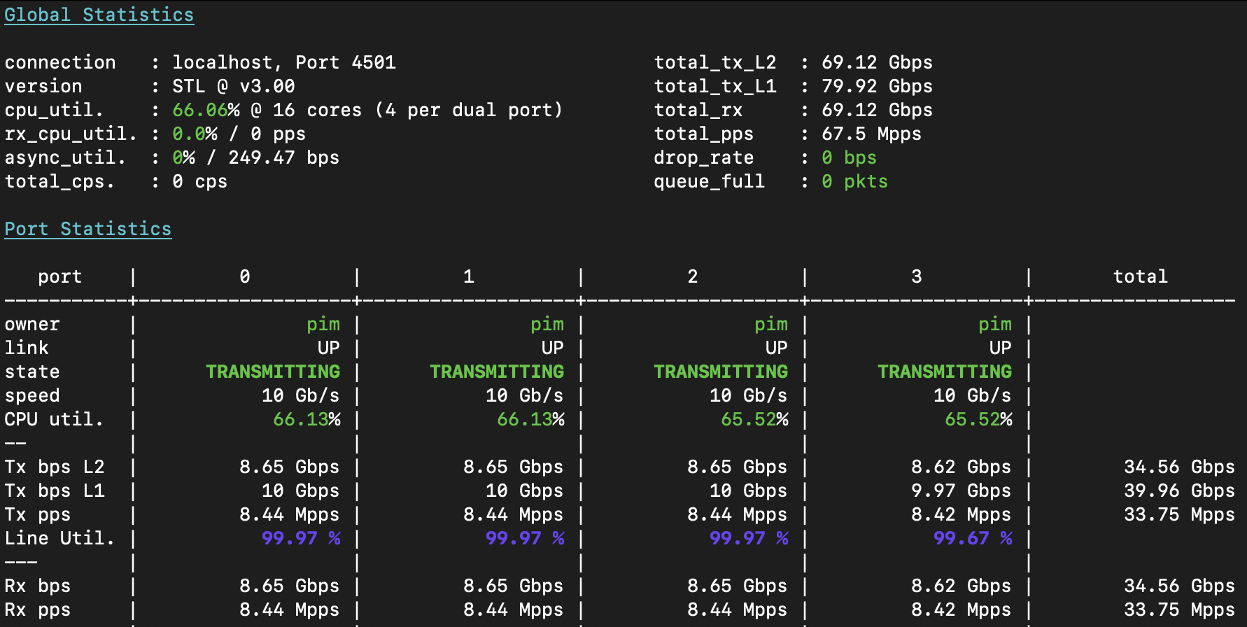
With that gripe out of the way, let’s take a look at 80Gbit of tunneled traffic, shall we?
Once again, all three switches are acing it. So at least 40Gbps of encap- and 40Gbps of decapsulation
per switch, and the transport over IPv4 through the msw-core switch to the other side, is all in
working order. On top of that, I’ve shown that multiple types of overlay can live alongside one
another, even betwween the same pair of switches, and that multiple VLANs can share the same underlay
transport. The only downside is the single flow nature of these UDP transports.
A final inspection of the switch throughput:
msw-top# show interface summary | exc DOWN
RXBS: rx rate (bits/sec)        RXPS: rx rate (pkts/sec)
TXBS: tx rate (bits/sec)        TXPS: tx rate (pkts/sec)

Interface    Link  RXBS          RXPS          TXBS          TXPS
-----------------------------------------------------------------------------
eth-0-1      UP    10013004482   8456929       10013004548   8456929
eth-0-2      UP    10013030687   8456951       10013030801   8456951
eth-0-3      UP    10012625863   8456609       10012626030   8456609
eth-0-4      UP    10013032737   8456953       10013034423   8456954
eth-0-25     UP    505           0             513           0
eth-0-26     UP    51147539721   33827761      51147540111   33827762
Take a look at that eth-0-26 interface: it’s using significantly more bandwidth (51Gbps) than
the sum of the four transports (4x10Gbps). This is because each ethernet frame (of 128b) has to be
wrapped in an IPv4 UDP packet (or in the case of NvGRE an IPv4 packet with a GRE header), which
incurs quite some overhead, for small packets at least. But it definitely proves that the switches
here are happy to do this forwarding at line rate, and that’s what counts!
Conclusions
It’s just super cool to see a switch like this work as expected. I did not manage to overload it at all, neither with IPv4 loadtest at 67Mpps and 80Gbit of traffic, nor with L2 loadtest with four ports transported with VxLAN, NvGRE and GENEVE, at the same time. Although the underlay can only use IPv4 (no IPv6 is available in the switch chip), this is not a huge problem for me. At AS8298, I can easily define some private VRF with IPv4 space from RFC1918 to do the transport of traffic over VxLAN. And what’s even better, this can perfectly inter-operate with my VPP routers which also do VxLAN en/decapsulation.
Now there is one more thing for me to test (and, cliffhanger, I’ve tested it already but I’ll have to write up all of my data and results …). I need to do what I said I would do in the beginning of this article, and what I had hoped to achieve with the FS switches but failed to due to lack of support: MPLS L2VPN transport (and, its more complex but cooler sibling VPLS).